TM-9-2350-261-20-2 - Page 847 of 1008
TM 9-2350-261-20-2
ADJUST ACCELERATOR AND TRANSMISSION THROTTLE VALVE
LINKAGE — Continued
0401 00
2.
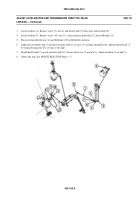
Remove two screws (6) and gauge (2) from governor (7).
NOTE
Gauge (2) is identified as part number 12269180 (NSN 5340-01-086-3243).
3.
Install gauge (2) in adjustment position on governor (7). Secure with two screws (6).
4.
Loosen screw (5) that secures governor throttle arm (1) to governor shaft (4).
5.
Align hole in governor throttle arm (1) with hole in gauge (2). Insert screw (3) through throttle arm and gauge.
6.
Insert 3/16 inch (5 mm) key socket head screw in plug on top of governor shaft (4). Turn to the right to rotate governor
shaft (4) to full throttle position and hold.
7.
Tighten screw (5) that secures throttle arm (1) to governor shaft (4).
8.
Remove screw (3) inserted in Step 5 above.
9.
Remove two screws (6) that secure gauge (2) to governor (7) and return gauge to stowed position. Secure gauge with
two screws (6).
10. Connect throttle link (7) to governor throttle arm (1). Secure with screw (3) and nut (8).
040100-3
Back to Top


