TM-9-2350-261-20-2 - Page 849 of 1008
TM 9-2350-261-20-2
ADJUST ACCELERATOR AND TRANSMISSION THROTTLE VALVE
LINKAGE — Continued
0401 00
3.
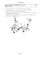
Loosen locknut (4). Remove screw (5), nut (6), and throttle link (7) from outer transfer shaft (8).
4.
Loosen locknut (9). Remove screw (10), nut (11), and accelerator pedal link (12) from bellcrank (13).
5.
Place governor throttle arm (14) and bellcrank (15) in full throttle position.
6.
Align holes in throttle link (7) and outer transfer shaft (8) so screw (5) will pass through freely. Shorten throttle link (7)
by turning bearing end (16) 11 turns to the right.
7.
Install throttle link (7) on outer transfer shaft (8). Secure with screw (5) and nut (6). Tighten locknut (4) on link (7).
8.
Adjust idle stop. See ADJUST IDLE STOP Steps 1 - 5.
040100-5
Back to Top


