TM-9-2350-261-20-2 - Page 854 of 1008
TM 9-2350-261-20-2
ADJUST ACCELERATOR AND TRANSMISSION THROTTLE VALVE
LINKAGE — Continued
0401 00
WARNING
Adjusting accelerator linkage while the engine is running can cause your arm to be badly
injured. Do not adjust accelerator linkage with the engine running.
8.
Remove driver’s and rear power plant access panels (WP 0430 00, WP 0431 00, WP 0432 00, or WP 0433 00).
9.
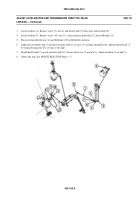
Loosen locknut (1). Remove screw (2) and nut (3) from throttle link (4) and transfer shaft (5). To decrease engine
RPM at shift point, shorten throttle link (4) by turning rod end (6) to the right. To increase engine RPM at shift point,
lengthen throttle link (4) by turning rod end (6) to the left. Attach throttle link (4) to transfer shaft (5) with screw (2)
and nut (3). Tighten locknut(1).
10. Readjust accelerator pedal stops by repeating the following procedures:
a.
Adjust Idle Stop.
b.
Adjust Upper Accelerator Pedal Detent Stop.
c.
Adjust Upper Accelerator Pedal Toe Stop.
d.
Repeat Check Operation.
FOLLOW-THROUGH STEPS
1.
Engine stopped/shutdown (see your -10).
END OF TASK
0401 00-10
Back to Top


