TM-9-2350-277-20-5 - Page 875 of 1047
TM 9-2350-277-20-5
REPAIR/REPLACE MORTAR FIRE CONTROL SYSTEM (MFCS) CABLES
(M577A3 ONLY) — Continued
0812 07
INSTALLATION
NOTE
Refer to TM 9-1220-248-23&P for wiring diagram.
1.
Position cables to ensure adequate lengths between connection points.
NOTE
Steps 2 - 8 apply to cable 4W7, power/data cable for commander’s interface.
2.
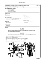
Locate P2 connector of cable 4W7 (12). Orient cable to right of PDA (11) on forward driver’s side shelf (21).
3.
Route P2 and P6 connectors of 4W7 (12) between forward driver’s side shelf (21) and wall.
CAUTION
To prevent damage to equipment, ensure power is turned off at power distribution assembly
(PDA) before connection of cable.
4.
Connect P2 connector of cable 4W7 (12) to J3 connector (15) on PDA (11).
5.
Connect P6 connector of cable 4W7 (12) to J1 connector (14) on CI (13).
NOTE
Refer to TM 9-1220-249-10 for radio setup procedures.
Refer to TM 11-5820-890-10-7 for information about the SINCGARS radio.
6.
Connect P8 and P9 connectors of cable 4W7 (12) to connection points on two SINCGARS radios (17) and (16) as shown
in TM 9-1220-248-23&P Block Diagram for Cable Installation. Coil P10 branch of cable 4W7 and place on radio rack.
7.
Secure cable 4W7 (12) to existing vehicle wiring. When necessary, install longer cable fastener to secure cable. See TM
9-1220-248-23&P.
8.
Coil P6 branch of cable 4W7 (12) and stow on cable hanger (20).
0812 07-6
Change 4
Back to Top


