TM-9-2520-270-34 - Page 292 of 933
TM 9-2520-270-34
REPAIR CONTROLLER STEERING CONTROL ARM
DESCRIPTION
This task covers: Disassemble (page 3-46). Assemble (page 3-49).
INITIAL SETUP
Tools:
General mechanic’s tool kit:
automotive — (Item 33, App C)
Industrial goggles — (Item 39, App C)
Inside/outside indicator caliper —
(Item 41, App C)
Machinist’s vise – (Item 47, App C)
Micrometer caliper set — (Item 53, App C)
Materials/Parts:
Lockwire — (Item 5, App B)
Transmission oil — (Item 12, App B)
Materials/Parts:
Cotter pin
Helical spring
(cont)
(2)
Personnel Required:
Track Veh Rep 63H10
Equipment Conditions:
Controller assembly on workbench. See
page 3-32.
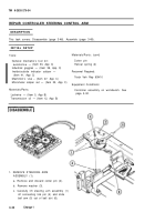
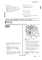
1. REMOVE STEERING ARM
ASSEMBLY (1).
a. Remove and discard cotter pin (2).
b. Remove washer (3).
c. Carefully lift steering arm assembly (1)
off connecting link pin (4) and slide
ball arm (5) out of ball slot (6).
3-46
Change 1
Back to Top


