TM-9-2815-200-35
ENGINE, WITH CONTAINER:TURBOSUPERCHARGED, DIESEL ,FUEL INJECTION ,90-DEGREE “V” TYPE, AIR - COOLED ,12 - CYLINDER , ASSEMBLY ;MODELS AVDS-1790-2M (2815-856-4996), AVDS-1790-2A AND AVDS-1790-2AM (2815-856-9005)
TECHNICAL MANUAL; DIRECT SUPPORT, GENERAL SUPPORT AND DEPOT MAINTENANCE MANUAL INCLUDING REPAIR PARTS AND SPECIAL TOOLS LISTS
TM-9-2815-200-35 - Page 260 of 779
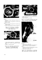
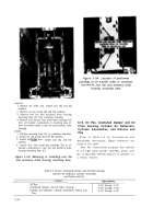
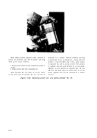
Figure 5-134. Location of preformed
packings at oil transfer tubes in crankcase
assembly- rear fan and accessory drive
housing mounting base.
Remove
1. Remove ten cotter pins, slotted nuts (A), and flat
washers.
2. Remove six cap screws (B) and flat washers.
3. Remove rear fan and accessory drive housing
mounting base (C) from crankcase assembly.
4. Remove and discard four preformed packings (D)
from oil transfer counterbores in mounting base (or
from oil transfer tubes in rear fan and accessory drive
housing).
Install
1. Position mounting base (C) on crankcase assembly.
2. Install six cap screws (B) and flat washers.
3. Install ten co,ter pins,
slotted nuts (A), and flat
washers.
4. Install four new preformed packings (D) in oil
transfer counterbores in rear fan and accessory drive
housing mounting base (C).
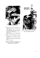
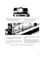
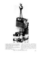
Figure 5-133. Removing or installing rear fan
and accessory drive housing mounting base.
5-12. Oil Pan, Crankshaft Damper and Oil
Filter Housing, Cylinder Air Deflectors,
Cylinder Assemblies, and Pistons and
Pins
Refer to Table 5-9 for illustrations an d
disassembly instructions. Figure references are
listed in the table.
Note.
For instructional purposes the removal
of one right bank cylinder assembly, piston, and
pin is described. Remove balance of cylinders in
a similar manner.
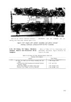
Table 5-9. Oil Pan, Crankshaft Damper and Oil Filter Housing,
Cylinder Air Deflectors, Cylinder Assemblies,
and Pistons and Pins
Component
Figure Reference
Oil Pan
5-135 through 5-137
Crankshaft Damper and Oil Filter Housing
5-138 through 5-140
Cylinder Air Deflectors, Cylinder Assemblies, Pistons and
5-141 through 5-147
Pins
5-74
Back to Top


