TM-9-2815-200-35
ENGINE, WITH CONTAINER:TURBOSUPERCHARGED, DIESEL ,FUEL INJECTION ,90-DEGREE “V” TYPE, AIR - COOLED ,12 - CYLINDER , ASSEMBLY ;MODELS AVDS-1790-2M (2815-856-4996), AVDS-1790-2A AND AVDS-1790-2AM (2815-856-9005)
TECHNICAL MANUAL; DIRECT SUPPORT, GENERAL SUPPORT AND DEPOT MAINTENANCE MANUAL INCLUDING REPAIR PARTS AND SPECIAL TOOLS LISTS
TM-9-2815-200-35 - Page 269 of 779
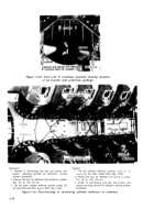
Note.
Do not remove crankcase protectors -
until
the
crankshaft
and
con-
netting rods have been removed (para 5-15).
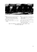
Figure 5-147. Engine with cylinder assemblies and pistons removed
showing crankcase protectors-4910-795-7951 installed.
5-13. Oil Pump, Oil Tubes, Vibration
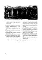
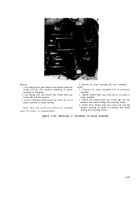
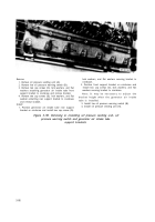
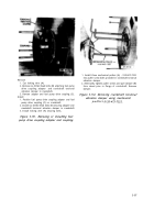
Refer to Table 5-10 for illustrations and
Damper, Starter and Generator Drive
disassembly instructions. Figure references are
Adapters
listed in the table.
Table 5-10. Oil Pump, Oil Tubes, Vibration Damper, Starter and
Generator Drive Adapters
Component
Figure Reference
Oil Pump, Oil Tubes and Oil Pressure Sending Unit and
5-148 through 5-150
Switch
Fuel Pump Drive Shaft Coupling and Crankshaft Torsional
5-151 and 5-152
Vibration Damper
Starter Drive Adapter and Starter Driven Gear
5-153 through 5-155
Generator Drive Adapter and Drive Gearshaft
5-156 through 5-158
5-83
Back to Top

