TM-9-2815-200-35
ENGINE, WITH CONTAINER:TURBOSUPERCHARGED, DIESEL ,FUEL INJECTION ,90-DEGREE “V” TYPE, AIR - COOLED ,12 - CYLINDER , ASSEMBLY ;MODELS AVDS-1790-2M (2815-856-4996), AVDS-1790-2A AND AVDS-1790-2AM (2815-856-9005)
TECHNICAL MANUAL; DIRECT SUPPORT, GENERAL SUPPORT AND DEPOT MAINTENANCE MANUAL INCLUDING REPAIR PARTS AND SPECIAL TOOLS LISTS
TM-9-2815-200-35 - Page 257 of 779
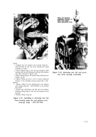
Remove
1. Remove ten cotter pins, slotted nuts (A), and flat
washers.
2. Remove two cap screws (B) and flat washers.
3. Remove and discard preformed packing (C) from oil
transfer tube counterbore in mounting base assembly
(D) (or from oil transfer tube in fan drive housing).
4. Remove front fan drive housing mounting base
assembly (D) from crankcase assembly.
Install
1. Position frunt fan drive housing mounting base
assembly (D) on crankcase assembly,
2. Install a new preformed packing (C) in oil transfer
tube counterbore in mounting base assembly.
3. Install two cap screws (B) and flat washers,
4. Install ten cotter pins, slotted nuts (A), and flat
washers.
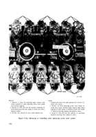
Figure 5-125. Removing or installing front
fan drive housing mounting base assembly
from crankcase assembly.
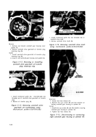
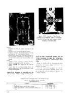
Figure 5-126. Location of preformed packing
at oil transfer boss in crankcase assembly.
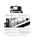
Remove
1. Remove and discard preformed packing (A) from oil
transfer tube in fuel injection pump mounting base.
2. Remove four bolts (B) and lock washers and remove
mounting base from crankcase assembly.
Install
Note.
Due to design change the curren t
engines use longer bolts and the addition of lock
washers. Check all bolts and discard any- that are
1-7
/
32-inch long. Replace with current 1-3
/
8-
inch bolts FSN 5305-725-0154 and lock washers
FSN 5310-584-5272 .
1. Position fuel injection pump mounting base on crank-
case assembly and install four bolts (B) and lock
washers and torque tighten to 750 pounds-inch.
2. Install a new preformed packing (A) in oil transfer
tube on mounting base.
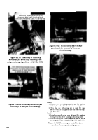
Figure 5-127. Removing or installing fuel
injection pump mounting base.
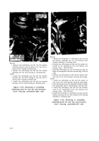
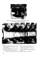
Figure 5-128. Location of preformed packing
at oil transfer tube for fuel injection
pump mounting base.
5-71
Back to Top


