TM-9-2815-205-24 - Page 755 of 856
ASSEMBLY - Continued
NOTE
Apply sealing compound to all uncoated plugs and fittings.
3.
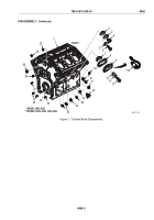
On model 5063-5392, install pipe plug (Figure 9, Item 14) in oil gallery hole at right side of cylinder block.
4.
On models 5063-5299, 5063-5393, and 5063-539L, install bushing (Figure 9, Item 15) and pipe plug
(Figure 9, Item 16) in oil gallery hole at right side of cylinder block.
5.
On models 5063-5392, 5063-5393, and 5063-539L, install pipe plug (Figure 9, Item 21) in dipstick hole at
left side of cylinder block.
6.
On model 5063-5299, install two pipe plugs (Figure 9, Item 21) in dipstick holes on each side of
cylinder block.
7.
Install new expansion plug (Figure 9, Item 27) in rear of cylinder block at upper right side. Expansion plug
must be flush to 0.030 in. (0.76 mm) below surface.
8.
Install two new expansion plugs (Figure 9, Item 26) in main oil gallery at ends of cylinder block. Expansion
plugs must be flush to 0.030 in. (0.76 mm) below surface of block.
9.
If removed, press four pins (Figure 9, Item 25) into rear main bearing cap (Figure 9, Item 24). Pins must
protrude 0.107–0.117 in. (2.72–2.97 mm).
10.
Install four pipe plugs (Figure 9, Item 20): one in left side of block, two in right side of block, and one in top
of left cylinder side.
11.
Install two draincocks (Figure 9, Item 18) in sides of cylinder block.
12.
Install new plug (Figure 9, Item 19), pipe plug (Figure 9, Item 17), and two pipe plugs (Figure 9, Item 22) in
right side of cylinder block. Plug must be flush to 0.030 in. (0.76 mm) below surface of block.
13.
Install four dowel pins (Figure 9, Item 23) into ends of cylinder block. Pins must protrude 11/16 inch
(17.46 mm).
27
FRONT
* MODEL 5063-5392
26
23
23
24
22
21
20
19
18
17
15
*14
16
20
25
20
MAINT_411
Figure 9.
Cylinder Block Assembly.
TM 9-2815-205-24
0098
0098-13
Back to Top


