TM-9-2815-205-24 - Page 751 of 856
INSPECTION-ACCEPTANCE AND REJECTION CRITERIA - Continued
NOTE
Main bearing caps are numbered to correspond with their respective positions in
cylinder block. No. 1 bearing cap is located at front of block and stamped on
bottom of front oil pan rail.
Install main bearing bolts, bearing caps, stabilizers, and hardened washers
(WP 0097).
7.
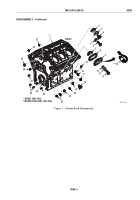
Using cylinder bore gage, measure diameters of main bearing bores (Figure 6, Item 36) with bearing caps in
original position. Diameter of main bearing bore is 3.751–3.752 in. (95.28–95.30 mm). If bores do not meet
these limits, replace cylinder block.
36
MAINT_408
Figure 6.
Main Bearing Bore Depth.
8.
Measure diameter of camshaft bearing bores. End bearing bores must be 2.3750–2.3760 in.
(60.325–60.350 mm) for standard bearings and 2.3850–2.3860 in. (60.579–60.044 mm) for oversized
bearings. Intermediate bearing bores must be 2.3650–2.3660 in. (60.071–60.096 mm) for standard bearings
and 2.3750–2.3760 in. (60.325–60.350 mm) for oversized bearings.
9.
Check remaining cylinder block surfaces and threaded holes for damage. Check all mating surfaces or
mounting pads for flatness, nicks, and burrs. Clean up damaged threads in tapped holes with a tap or install
helical thread inserts if necessary.
10.
Check for cracking in area between center water transfer holes and cylinder head to block bolt holes
(cam and exhaust sides). If cracks are found, replace cylinder block.
END OF TASK
TM 9-2815-205-24
0098
0098-9
Back to Top


