TM-9-2815-205-24 - Page 754 of 856
ASSEMBLY - Continued
2.
Install four camshaft end bearings (Figure 8, Items 31 and 28) as follows:
a.
Insert pilot (Figure 8, Item 32) in bore of cylinder block. Use small diameter of pilot if bearing has been
installed. Use large diameter if there is no bearing in block.
b.
Insert support (Figure 8, Item 45) in end bore at opposite end of block.
c.
Start unthreaded end of shaft (Figure 8, Item 33) into pilot (Figure 8, Item 32) and push through block
and support (Figure 8, Item 45).
d.
Place end bearing (Figure 8, Items 31 or 28) on installer (Figure 8, Item 38) and align notch in bearing
with pin on installer. Slide bearing and installer on shaft (Figure 8, Item 33). Ensure notch in bearing is
positioned properly in bore as shown.
e.
Place C-washer (Figure 8, Item 37) in groove near end of shaft (Figure 8, Item 33). Pull shaft back
until C-washer butts against installer (Figure 8, Item 38).
f.
Place spacer (Figure 8, Item 44) (if required), thrust washer (Figure 8, Item 43), flat washer
(Figure 8, Item 42), and hex nut (Figure 8, Item 41) over threaded end of shaft (Figure 8, Item 33).
g.
To draw bearing (Figure 8, Items 31 or 28) into position, turn hex nut (Figure 8, Item 41) until shoulder
on installer (Figure 8, Item 38) butts up against block bore.
h.
Remove bearing installer (Figure 8, Item 38) assembly from cylinder block.
i.
Repeat Steps 2.a.–2.h. for remaining end bearings.
62°
62°
37
45
32
BEARING NOTCH ANGLE
33
41
42
43
44
38
28, 31
MAINT_410
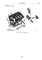
Figure 8.
Cylinder Block Bearing Assembly.
TM 9-2815-205-24
0098
0098-12
Back to Top


