TM-9-2815-205-34 - Page 389 of 596
TM 9-2815-205-34
(b)
(c)
(d)
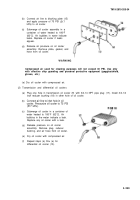
Connect air line to blocking plate (15)
and apply pressure of 75 PSI (517
kPa) to oil cooler.
Submerge oil cooler assembly in a
container of water heated to 180°F
(82°C). Air bubbles in water indicate
leaks. Replace oil cooler if leaks
appear.
Release air pressure on oil cooler
assembly. Remove plate, gasket, and
hose from oil cooler.
Compressed air used for cleaning purposes will not exceed 30 PSI. Use only
with effective chip guarding and personal protective equipment (goggles/shield,
gloves, etc.)
(e) Dry oil cooler with compressed air.
(2) Transmission and differential oil coolers
(a)
(b)
(c)
(d)
(e)
(f)
Plug one hole in transmission oil cooler (9) with 3/4-14 NPT pipe plug (17). Install 3/4-1/4
inch reducer bushing (18) in other hole of oil cooler.
Connect air line to inlet hole in oil
cooler. Pressurize oil cooler to 75 PSI
(517 kPa).
Submerge oil cooler in a container of
water heated to 180°F (82°C). Air
bubbles in the water indicate a leak.
Replace any oil cooler with a leak.
Release pressure on oil cooler
assembly. Remove plug, reducer
bushing, and air hose from oil cooler.
Dry oil cooler with compressed air.
Repeat steps (a) thru (e) for
differential oil cooler (10).
3-259
WARNING
Back to Top

