TM-9-2815-205-34 - Page 430 of 596
TM 9-2815-205-34
3-64. CYLINDER HEAD ASSEMBLY REPAIR (Cont)
NOT E
Valve seat counterbore has a diameter of 1.159-1.160 inches (29.44-29.46 mm) and a
depth of 0.294-0.306 inch (7.47-7.77 mm). Counterbores must be concentric with
valve guides within 0.003 inch (0.08 mm) total indicator reading.
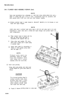
(d) Immerse cylinder head in water heated to 180-200°F (82-93°C) for 30 minutes or cool
insert with liquid nitrogen.
NOT E
Install valve seat in cylinder head while head is still hot and valve seat is at room
temperature or when valve seat is chilled with liquid nitrogen and cylinder head is at
(e)
(f)
(g)
room temperature.
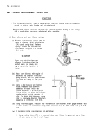
Place cylinder head on bench with fire
deck up. Place valve seat (68) in
counterbore with tapered face up.
Using valve seat installer (70), drive
valve seat in place until it seats solidly
in cylinder head.
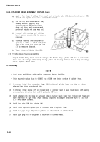
Check valve seats for concentricity in
relation to valve guides using valve
seat dial gage (71).
NOT E
Exhaust valve seats are
prefinished. Check for concen-
tricity after installation. Grind
valve seats only if runout
exceeds 0.002 inch (0.05 mm).
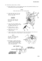
(5) Valve seat grinding
Using valve seat grinder and valve seat
grinder adapter kit, grind valve seats as
follows:
CAUTION
(a)
Do not permit grinding wheel to
contact cylinder head when
grinding valve seat. If valve
seat is ground until grinding
wheel contacts cylinder head,
then install new valve seat.
Apply 31 degree grinding wheel on valve seat.
3-300
Back to Top


