TM-9-2815-205-34 - Page 432 of 596
TM 9-2815-205-34
3-64. CYLINDER HEAD ASSEMBLY REPAIR (Cont)
CAUTIO N
•
The difference in load of a pair of valve springs under one bracket must not exceed 6
pounds or exhaust valve bracket will be unbalanced.
•
Replace both springs under an exhaust valve bracket together. Mating a new spring
with a used spring can cause unbalanced valve operation.
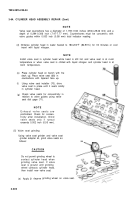
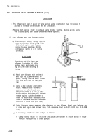
(7) Cam followers and cam follower springs.
(a) Examine cam follower springs (26) for
wear or damage. Using spring tester
(74), check spring Ioad. Replace
spring if a load less than 250 Ibs
compresses spring to 2.14 inches
(5.44 cm).
CAUTION
(b)
(c)
(d)
(e)
Do not use fuel oil to clean cam
followers. Lubricating oil will be
washed away and cause scor-
ing of cam roller bushing at
startup.
Wash cam followers with engine oil
and wipe dry. Examine rollers for
pitting, scoring, and flat spots. Rollers
(75) must turn freely on their pins
(76).
Using a dial indicator and holding
fixture, measure total diametric
clearance on roller. Install cam
follower assembly in a vise or other
holding device and place dial indicator
needle against outside diameter of
roller. To obtain total clearance, move
roller in crosswise direction. Maximum
clearance is 0.010 inch (0.03 mm).
Using thickness gages, measure side clearance on cam follower. Insert gage between end
of roller and leg of cam follower body. Side clearance must be 0.011-0.023 inch (0.28-0.58
mm).
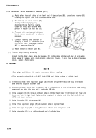
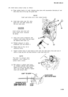
If necessary, install new roller and pin as follows:
1. Clamp holding fixture (77) in a vise and place cam follower in groove at top of fixture
with pin resting on top of small plunger.
3-302
Back to Top


