TM-9-2815-210-34-2-1 - Page 190 of 259
TM 9-2815-210-34-2-1
b .
Engines LDS-465-1 and LDS-465-1A.
CAUTION
Do not make a punch mark anywhere on pressure plate
assembly (1) except where pressure plate assembly is
flush with rim of flywheel (2). Pressure plate assembly
could be bent.
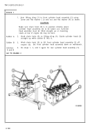
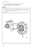
1.
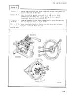
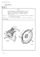
Make a punch mark on pressure plate assembly (1) and rim of flywheel (2)
as shown.
Both marks should be next to each other so pressure plate as-
sembly and flywheel can be alined during engine assembly.
NOTE
There are many holes in pressure plate assembly (1).
Only three holes have a threaded sleeve behind them
for retaining screws (3).
The location of these holes
is different on different pressure plate assemblies.
The right holes may be hard to find because threaded
sleeves are inside springs (4).
2.
Using strong light, look through big hole in center of pressure plate assembly
(1). Find the three holes with threaded sleeves behind them.
3.
Put 3/8 - 16 x 2 1/4-inch retaining screw (3) and 1 1/4-inch outside
diameter, 1 /8-inch thick flat washer (5) into the three holes found in
step 2.
Tighten three retaining screws (3) evenly to take spring pressure
off clutch disk on flywheel (2).
GO TO FRAME 2
TA 087691
3-142
Back to Top

