TM-9-2815-210-34-2-2 - Page 264 of 968
TM 9-2815-210-34-2-2
FRAME 7
1.
2.
3.
4.
NOTE
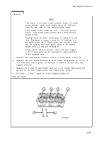
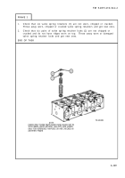
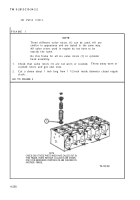
This frame is for early model cylinder heads (1). Early
model cylinder heads used intake valves (2) different
from the ones used on late model cylinder heads.
Early model intake valves (2) have a dull shot peened
finish.
Late model intake valves have a shiny chrome
plated finish.
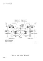
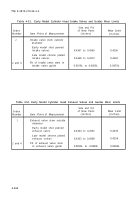
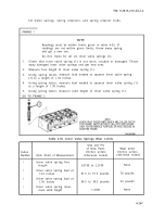
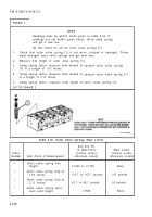
Readings must be within limits given in tables 4-53 and
4-54. The letter L shows a loose fit.
If readings are
not within given limits, throw away part and get a new
one. Be sure to use limits which apply to the type of
intake valve (2) you are working on.
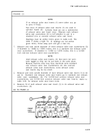
Intake valves (2) and exhaust valves (3) were tagged
so fit of each valve can be measured in valve guide (4)
it was removed from.
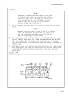
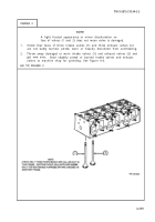
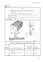
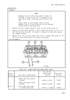
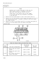
Measure and note outside diameter of stem of three intake valves (2).
Measure and note inside diameter of three intake valve guides (4) 1/8 to 1/4
inch from each end of guide.
If diameter is different at each end, note
biggest diameter.
Measure fit of stem of each
Do this for all three intake
Do steps 1, 2, and 3 again
END OF TASK
intake valve (2) in its intake valve guide (4).
valves and intake valve guides.
for three exhaust valves (3).
4-245
Back to Top

