TM-9-2815-210-34-2-2 - Page 270 of 968
TM 9-2815-210-34-2-2
FRAME 2
1.
2.
3.
4.
5.
6.
7.
NOTE
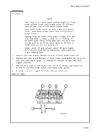
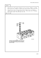
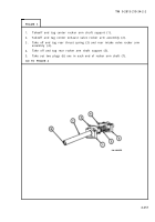
Do this frame for all six valve rotors (1) in cylinder head
assembly.
Draw a chalk mark across inner section (2) and outer section (3) of valve
rotor (1) as shown.
Put rotor (1) in a container of clean engine oil.
Put short steel sleeve (4) on platform of spring tester (5) as
shown.
Take rotor (1) out of container of oil. Let excess oil drip off. Put rotor (1)
on sleeve (4) with valve spring seat side down as shown.
Put 3/4-inch hardened steel ball (6) on top of rotor (1) as shown.
Work spring tester (5) to put a load of 260 pounds on ball (6) on top of valve
rotor (1).
Then let up load to 110 pounds.
Do step 6 again 25 to 30 times.
Check that marks on inner section (2) and
outer section (3) of valve rotor (1) move apart as shown. If marks do not
move apart, throw away valve rotor and get a new one.
END OF TASK
4-251
Back to Top

