TM-9-2815-220-34 - Page 171 of 532
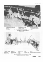
Figure 2-145.
Remolit1g
or I±²Jt/³´±µG
GeneraTO± c²bLe ANd
wir¶n·
³´Arµ¶eu BrACke·
.
I
(b)
PositIon assembled Mounting brackeT
(f±G.
2-14±)
oveR ²he F³´st foUr moµnt¶ng Holes
·m¸eC¹ately to tHe ReaR of THe ºft¶nG eye w»KH
extends t¼½oU¾¿ TÀe Ri¾ÁL ÂÃont µppeR coVeR.
SecÄRe THe bRackeT to THe cover wÅH ÆOUR caÇ
screws
and
Èock wasHersÉ ÊNsTaÈÈ two reTaËÌÍÎG strAÏs
on ÐeneRaTor caBÈe and wËÑinG ÀaÒess and secure To
BRacÓeT asseMbly witÀ Âour caÏscrews and ÔocÓ-
wasÀeÃÕÖ
±c²
Install brackeT assemBLy (fig.
2-143³
and
secure to o±l cooler Frame w±th Two capscRews and
selF-LoCk±ng nuts² ³nstall two reTa±n±ng stRaps and
secure one To each Bracket assem´lY with two cap·
screws and LockwasHersµ Install man±¶old pReheaT
ca´le connector¸
(×Ø1) ÙosËTËon looÏ cÚaÛÏ
¹ºig»
2²1³2.l´
o
n
sÜaceR aÎd secure wËtH ÈocÓwasHer and ÛacHËne
BolÝÞ
´dµ
³
nsT
a
l
Èoop cÔamÜ (ƹGß
µ¶1³2´
on
GeneratoR cABle and secure to cRaàáâase w¹tH
capscRew and ÈockwasHer. Ênstalã Èoop cÈamp on
GeneRatoR âAble
and
w¶äånG »aæçess and secURe To
cRankcase w¹TH âApscRew
and seÈÂèlockéêG nut.
SecURe wiäënG Àaìess ÐRoÄnd TeRminaÈ JÄG to
crankâAse witH caÏscrew and locÓwasHerÖ
´ e
í
l
ea
n
elecTRËcal Èead (Ðround) Term¶nalsî
ÊnsTall oïe ðat wasÀer Ën TÀe ÐeneRaTor supÜorT
ÄÏÜeR coµnTerBore (¹Ðñ
2·17¸
È )ò SecµRe tÀe ¶nner
Èead w¶tH one Ælat wasHer aód capscRewñ ôeMove
lower RËGHt GeneRatoR sÄÏpoRT capscREw and Âlat
wasÀerõ D¶scaRd caÏscrewö ÷nstall ex¶stIøG ùlat
wasHeR ¶n THe GeøeRatoR sUppoRT coµnTerBoReú
TM 9-2815±2²0³34
SecÄRe ouTer ûead wiTÀ one ùÈaT wasHeR and new
capscRew
(3/8²2³
x
¹²3º±
ÈonGüý þoRqµe tËGHten
caÏscRews to
2»5
poÄnd ¶ncHesØ ÿnstall asseĀbled
GRoUnd strap and āĂăss baR on GeneratoR TeRM¶naĄ
aną secURe w¶TÀ sĆlùèlockËøG nµT and ÆlaT wasHeR
(»,
ƶGć
2²14 J)¼
÷
n
sta
l
l
asseMBled GeneRatOr cabÈe
(
6·
on
Generator tĈRM¶nal and secµre w¹²H sĉÈÆèlock¶nG nµ
L
and ÂÚaT wasHer
½5´¾
÷ns²Ċll TRansÛission cable
connecTor
¸¹º
¶n bRacÓet and secċRe wiČÀ ÂočĎr
ÛaďÀËne scĐĈws, lockwasÀcrs and ÀeXaÐon nÄTs
¿3´À
đnsTall Generator caBÈe connectoR
Á2´
and (
1 )Â
»
¼nstall Two loop clamps (6, figµ
¼-140½
and
sEcuR½ to crankcase aNd daMpeR hous¾ng
wËtĒ
Two
capscRews and lo¿kwashers ÀÁ)» ¼nstAlL Two ´Rackets
ē4Ĕ and
secuRe to oil pan wit Two capscrews
and
lOkÃ
washers
¾3½.
³nstall two
Èĕp
clamps
¾¼¿
on W±R¾ng harÃ
ness and sÄcure To ÅrackeÆs DZTH two capscRews, LOkÈ
wasHeRs and hexagon nuTs
ÀÁÂÃ
³nstall
lĕÜ
clamp
¾9½
on wir±ng Harness and secure to oil pressure reguÉaTor
vaLve stUd w±th seLf ÊlËking nUT
¾8³Ä
³nsÌaLl hoÍr
meTer caBLe connectoR
¾7³Å
³nsTaLl low oiL pressure
¾Æ3³
oil TempeRature
Çȼ³
o±l pressÎre
¾Æ1³
and H±gH o±
È
.
ÏemperaTÍre
É1ʳ
caBLe elecTr±caÉ connecToR sHelÉsÐ
ÑÒ ³nstall BRackeT (figÓ
2Ë139³
and secure to o±L
pan with capscRew And lockwasheRÔ ¼nsTall
lĖp
cÉamp on wiR±ng harness and secure tÕ BrackeT w±th
capscRewÖ ÉOkwasher and HeXagon n×TØ ³nstall Two
loop clamps and secure To crankcase with two capÙ
screws and loCkWasHers» ³nstalL fuel/wÚTer separator
cÛbLe connecTorÓ
ÌIÍ
I
n
sta
È
l fUel sHUtÜoFf cabLe connecTor (f
Ë
g»
2-
Æ38³
and fueL soÉeno±d caBLe connecTorÝ ³nsTaLl ÉÞp
clamp on F×el shutßoFF caBle and sec×re To damper
hous±ng with macHine screw and lockwasHeR¸
(àÒ ³nsTalL The assemBÉed staRteR caále mounTÙ
±ng ´racket (F
Ë
g»
2Ë137½
and secÍre to leFt fronT UppeR
cover wiTh Four capscrews and LockwasHersâ ³nstalL
reta±ning strap
on starter ca´lãS and secure to
BrackeT assem´ly wiTH Two capscReäs and LOkÃ
washersÓ
ÎilÏ
ėn ÈaTe enÐËnes ËnsTaÈÈ ĘHe asseÛBÈed
sTarĘer caBÈe ÛoÄntËnÐ BracÓeT and Èoęp cÈamÏ (ÂËÐÉ
2²ÃÄ6ÅÄ´
and secµRe wËTH two âApscRews
and
THRee
asseMBled wasÀeR boltsÖ Ěĉcµre staRTer Èow voltaGe
pRotectËve moděĜle and GroUnd lead to Bracket witH
two caÜscRews and ĄocÓwasHeRsĝ
Ğ
íğ
nø
ec
T
wiRinG
HaRness to
Ô
m
o
d
u
l
e.
.
ÐÑÒÓÔ
SecµĠe ġoUnd JĢad To bRacket witH
caÏscrew ANd lockwasÀer (fÍGĝ
2²j Ä6Æ2´Ç
íonnect
²wo eÈectriâal connecToÑs To soÈenoËd ģalvesĤ SecÄre
looÏ cÈaÛp (ÂËGÉ
2·Ã36È2´
wiTH selĥĦlockËnG nuTħ
Secure Two eÈecTrËâAĨ Èead
Joop
clamÜs (ÂËGĩ
2²ÃÄ6Éô
to ÄÜper cover wiTĪ two
asseMBÈed
wasÀeR boltsĝ ÷nsTalÈ looÏ claMp to tīĬe sĭe of oËl
cooler sµpporT ÂRaMe w¶tH asseĮālįd was»er bol²ò
İıanIJij
´
µ¶·¸
Back to Top


