TM-9-2815-225-34-P - Page 464 of 736
TM 9-2815-225-34&P
0049 00
0049 00-2
BIG CAM I ENGINE INSTALLATION (Contd)
1.
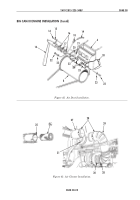
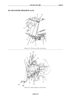
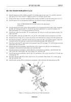
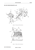
Attach two lifting brackets (4) with four bolts (3), lifting sling, and lifting device to engine (5).
WARNING
Use extreme care when handling heavy parts. Provide adequate
support and use assistance during procedure. Ensure that any
lifting device used is in good operating condition and of suitable
load capacity. Keep clear of heavy components supported only
by lifting device. Failure to do so may result in death or injury
to personnel.
Use pry bars to free engine hangups or snags. Do not use
hands. Failure to do so may result in damage to equipment or
death or injury to personnel.
2.
Using lifting device, lifting sling, and assistant, position engine over vehicle frame (22).
3.
Position two rear vibration insulators (23) and rear frame flat washers (24) on rear frame engine
mounting brackets (2).
4.
Position two front vibration insulators (7) and front frame flat washers (6) on front engine
crossmember (11).
5.
Using lifting device and lifting sling, lower engine (5) into vehicle frame (22). Ensure there is proper
clearance between power steering pump (8) and alternator (13) during lowering of engine (5).
NOTE
Use suitable drift pin to align mounting holes as nessessary.
6.
Secure engine (5) to two rear engine mounts (2) with two rear engine mount bolts (1),
washers (16), and nuts (15). Tighten nuts (15) finger-tight.
7.
Secure engine (5) to front engine crossmember (2) with two front engine mount washers (9),
bolts (10), and nuts (12). Tighten nuts (12) finger-tight.
8.
Remove lifting device, lifting sling, and lifting brackets (4) from engine (5).
NOTE
Rotate engine using accessory drive pulley nut to install
flywheel bolts.
9.
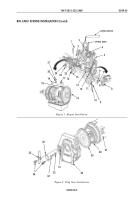
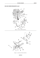
Using suitable drift pin and transmission jack, align transmission mounting holes (14) to flywheel
housing mounting holes and install twelve transmission bolts (17). Tighten bolts (17) 60 lb-ft (80 N
•
m).
10.
Attach ring gear (29) to flywheel (28) with twelve flywheel washers (32) and bolts (33) through
flywheel bolt access hole (31). Alternately tighten bolts (33) 42–48 lb-ft (57–65 N
•
m).
11.
Tighten two rear engine mount nuts (15) 270–295 lb-ft (366–400 N
•
m).
12.
Tighten two front engine mount nuts (12) 270–295 lb-ft (366–400 N
•
m).
13.
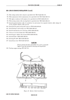
Install transmission temperature sender electrical connector (19), washer (20), and nut (21) on
transmission temperature sender (18).
14.
Position breather tube clamp (25) and install flywheel bolt access cover (26) on flywheel
housing (30) with two flywheel bolt access cover screw (34). Tighten screws (34) 15–20 lb-ft
(20–27 N
•
m).
15.
Remove transmission jack from under transmission (27).
Back to Top

