MWO-5-2350-262-35-4 - Page 23 of 207
MWO 5--2350--262--35--4
2--4
SECTION II INSTALLATION OF HDC CONTROL BOX STOWAGE FIXTURE --
CONTINUED
NOTE
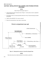
Steps e through h below apply to Figure 2--1.
e.
Using mounting hole location information shown in Figure 2--1, mark locations on driver’s compartment
rear wall to drill two holes.
f.
Drill and tap two holes on rear wall using 25/64” drill bit and 7/16” tap. Ensure all warnings are heeded
during drilling.
g.
Install two inserts, MS51831--102, in holes on rear wall.
h.
Ensure floor area behind driver’s seat location is clean and dry.
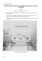
Figure 2--1. Mounting Hole Locations for Control Box Stowage Fixture
NOTE
Clean rubber strips and use rubberized adhesive to bond rubber to painted floor.
Back to Top

