MWO-5-2350-262-35-4 - Page 24 of 207
MWO 5--2350--262--35--4
2--5
SECTION II INSTALLATION OF HDC CONTROL BOX STOWAGE FIXTURE --
CONTINUED
NOTE
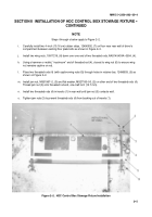
Steps i through o below apply to Figure 2--2.
i.
Carefully install two 4--inch (10.16 cm) rubber strips, 12496932, (7) on floor near rear wall of driver’s
compartment between existing floor plate bolts as shown in Figure 2--2.
j.
Install two wing nuts, 10917219, (6) down over one end of two threaded rods, NAS1454C4A--0504, (4).
k.
Using a hammer or mallet, “mushroom” end of threaded rod (4), closest to wing nut (6) to ensure wing
nut remains captive on rod.
l.
Place two threaded rods (4) (with captive wing nuts (6)) through holes in retainer bar, 12496933, (5) as
shown on Figure 2--2.
m. Install jam nut, MS51967--2, (3) and flat washer, MS27183--50, (2) on other end of two threaded rods (4).
Thread jam nut (3) onto threaded rod end, one--half inch (12.7 mm).
n.
Install two threaded rods (4) in inserts (1) in rear wall until jam nut (3) contacts wall.
o.
Tighten jam nuts (3) to prevent threaded rods (4) from backing out of inserts (1).
Figure 2--2. HDC Control Box Stowage Fixture Installation
Back to Top

