MWO-5-2350-262-35-4 - Page 33 of 207
MWO 5--2350--262--35--4
3--4
SECTION II INSTALLATION OF HDC PRIMARY MANIFOLD ASSEMBLY,
MANUAL SHUT–OFF VALVE V23, AND LEFT MAIN MANIFOLD PRESSURE
TRANSDUCER T7 -- CONTINUED
3--1
REMOVAL/DISASSEMBLY OF DCV BANK, SUSPENSION VALVE AND OTHER
ITEMS TO ACCOMMODATE INSTALLATION -- CONTINUED
d.
Remove split pipe flange, attached hydraulic hose and second hydraulic hose from the back of the DCV
bank before removing the DCV bank from the bowl and mounting brackets.
e.
Remove six cotter pins and disconnect mechanical control linkages from DCV bank valves per TM
5--2350--262--20--2, Directional Control Valve Bank Replacement. Discard six cotter pins.
f.
Detach, but do not disassemble, DCV bank from mounting brackets per TM 5--2350--262--20--2,
Directional Control Valve Bank Replacement. Discard locknuts, but save four mounting screws and flat
washers for reuse.
NOTE
Steps g through i below apply to Figure 3--1.
g.
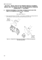
Remove four locking screws (1) and four flat washers (5) attaching split pipe flange (2) to back of DCV
bank (3). Discard locking screws but save flat washers.
h.
Disconnect hydraulic hose (4) from same area on back of DCV bank (3). DCV bank is now free to be
moved.
i.
Move DCV bank (3) from bowl area and place on flat, level surface capable of supporting sixty pounds.
Figure 3--1. Components to be Removed from DCV Bank -- Split Flange Assembly
Back to Top

