MWO-5-2350-262-35-4 - Page 34 of 207
MWO 5--2350--262--35--4
3--5
SECTION II INSTALLATION OF HDC PRIMARY MANIFOLD ASSEMBLY,
MANUAL SHUT–OFF VALVE V23, AND LEFT MAIN MANIFOLD PRESSURE
TRANSDUCER T7 -- CONTINUED
3--1
REMOVAL/DISASSEMBLY OF DCV BANK, SUSPENSION VALVE AND OTHER
ITEMS TO ACCOMMODATE INSTALLATION -- CONTINUED
NOTE
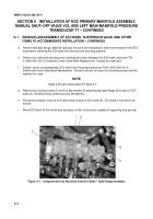
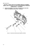
Steps j through m below apply to Figure 3--2.
j.
Remove and save elbow, MS51521A10, (7) from adapter, MS515A26A10, (6) installed on DCV bank
ejector forward port 21 (8).
k.
Remove and discard adapter, MS51526A10, (6) and o--ring, MS28778--10, (1) from DCV bank ejector
forward port 21.
l.
Remove and discard elbow, MS51521A8, (5) from DCV bank ejector retract port 22 (9).
m. Remove and discard elbow, MS51521A8, (4) adapter, AC--1--310, (3) and o--ring, MS28778--8, (2) from
DCV bank winch pay--out port C1 (10).
NOTE
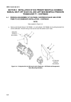
If difficulty is encountered in removing hydraulic hoses from suspension
(sprung/unsprung) valve when removing valve from bracket, remove mounting bracket
from bowl with valve and hoses still installed. Remove valve (with hoses attached) from
bracket after bracket is removed (in step q) from bowl.
n.
Remove cotter pin and disconnect mechanical control linkage from suspension valve per
TM 5--2350--262--20--2, Hydraulic Control Levers, Bellcranks, and Linkage Replacement and Repair.
Discard cotter pin.
o.
Remove, but don’t disassemble, suspension (sprung/unsprung) valve from mounting bracket per
TM 5--2350--262--20--2, Sprung/Unsprung Valve Replacement. Discard locknuts but save four mounting
screws and flat washers for reuse.
Back to Top

