MWO-5-2350-262-35-4 - Page 30 of 207
MWO 5--2350--262--35--4
3--1
CHAPTER 3
MODIFICATIONS IN BOWL AREA
SUBJECT:
Major modifications in the bowl area include the addition of a primary manifold assembly; three manually
operated ball valves and other associated hydraulic system components. In addition,an existing pressure reliefvalve
is relocated from the lower, left rear portion of the bowl area to the main filter area. There are a total of seven pressure
transducers added to this area of the vehicle: two transducers in the filter area, three transducers on the new primary
manifold assembly, one transducer on the pressure switch, and one transducer on the left main manifold.
DATE:
29 August 2008
DESCRIPTION:
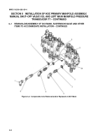
The primary manifold assembly is added in the area just beneath the directional control valve bank
and requires the addition of a new set of mounting brackets to accommodate the directional control valve bank and
the new primary manifold assembly.
The three manually operated ball valves provide safety features to use when personnel work in the bowl area. The
ball valves, related transducers, and other additional hydraulic components are integrated into the high--pressure hy-
draulic filter area. The existing pressure relief valve relocated from the lower, left rear portion of the bowl area is part
of the modification to the main filter area. Additionally, a pressure transducer is added to hydraulic circuits at the bot-
tom of the bowl area.
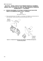
To accommodate the installation of the primary manifold assembly, the directional control valve (DCV) bank and the
existing mounting plates for the DCV bank must be removed and new mounting plates installed. The new mounting
plates properly secure both the directional control valve bank and the primary manifold assembly in the bowl area.
One of the new ball valves is installed near the control valve assembly and the primary manifold assembly. The other
two ball valves are mounted on the high--pressure hydraulic filters. A pressure transducer is mounted on each of the
high--pressure hydraulic filters above the control valve assembly in the bowl area.
Some existing parts/components are modified as part of the modification to the bowl area, and some parts are
removed and discarded.
TM REFERENCES
: The technical manual references in this procedure are for:
TM 5--2350--262--10, dated June 1992, with Change 7, dated June 2007
TM 5--2350--262--20--1, dated January 1997, with Change 4, dated July 2007
TM 5--2350--262--20--2, dated January 1997, with Change 4, dated July 2007
Back to Top

