TB-9-2510-251-13 - Page 37 of 624
2-21
TB 9-2510-251-13
2-1.1
Installation of Air Conditioning Kit to M998 and M998A1; M1037; M1097 and M1097A1
with GSIE Add-on-Armor (Cont’d).
c. Install Drier
CAUTION
DO NOT leave drier uncapped for more than just a few minutes as it will absorb
moisture out of the air and become unstable.
Failure to comply could result in
damage to equipment
.
1
2
5
4
3
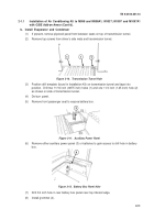
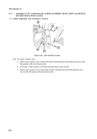
Figure 2-29.
Pressure Switches
Figure 2-30.
Band Clamps
(1)
Remove screw on caps from ports on top of receiver/drier (1).
NOTE
Pressure switch wire connectors are different and must be connected to the
correct switch on the harness.
If connector does not snap on with minimal
pressure, try other switch.
(2)
Lubricate O-rings and attach pressure switches (2) to ports.
Switches can be installed on
either port.
NOTE
For ease of installation, pre-bend end of band clamps prior to inserting in
slots on driver’s side condenser mount angle.
(3)
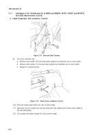
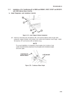
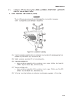
Install band clamps (3) on driver’s side condenser mount angle (4).
(4)
Position receiver/drier (1) with inlet (male) fitting under condenser fittings and outlet
(female) fitting pointing over top of armor plate.
(5)
Install receiver/drier in band clamps (3).
(6)
Connect condenser harness (5) to pressure switches (2) on receiver/drier (1).
Back to Top

