TB-9-3950-253-13-P
PALLETIZED LOAD SYSTEM TRUCK, M1075 and M1075A1 (PLS) AND HEAVY EXPANDED MOBILITY TACTICAL TRUCK, M1120, M1120A2, AND M1120A4 (HEMTT), ENHANCED CONTAINER HANDLING UNIT (E-CHU)
TECHNICAL BULLETIN; OPERATOR AND FIELD MAINTENANCE, INSTALLATION INSTRUCTIONS, AND REPAIR PARTS AND SPECIAL TOOLS LIST
JULY 2009
TB-9-3950-253-13-P - Page 538 of 704
TB 9-3950-253-13&P
Change 1
0052-28
0052
PLS STOWAGE ASSEMBLY INSTALLATION – CONTINUED
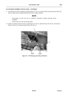
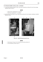
11. Loosen three locking pins (Figure 26, Item 1) and remove manifold cover (Figure 26, Item 2) from stowage
assembly (Figure 26, Item 6).
NOTE
•
Pressure hose is marked with “P” on manifold.
•
Relief hose is marked with “T” on manifold.
12. Identify pressure hose (Figure 26, Item 4) and relief hose (Figure 26, Item 3) based on markings on manifold
(Figure 26, Item 5).
Figure 26.
Identify Stowage Hydraulic Hoses.
052
NOTE
•
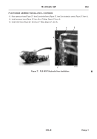
Perform steps 13 through 15 for PLS M1075 and continue with step 19.
•
For PLS M1075A1 proceed to step 16.
467-109
5
4
3
1
2
6
Back to Top


