TB-9-3950-253-13-P
PALLETIZED LOAD SYSTEM TRUCK, M1075 and M1075A1 (PLS) AND HEAVY EXPANDED MOBILITY TACTICAL TRUCK, M1120, M1120A2, AND M1120A4 (HEMTT), ENHANCED CONTAINER HANDLING UNIT (E-CHU)
TECHNICAL BULLETIN; OPERATOR AND FIELD MAINTENANCE, INSTALLATION INSTRUCTIONS, AND REPAIR PARTS AND SPECIAL TOOLS LIST
JULY 2009
TB-9-3950-253-13-P - Page 544 of 704
TB 9-3950-253-13&P
Change 1
0052-34
0052
PLS STOWAGE ASSEMBLY INSTALLATION – CONTINUED
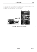
25. Release air pressure from system (TM 9-2320-364-14&P).
26. Remove two hoses (Figure 32, Item 1) from original fitting (Figure 32, Item 6).
27. Remove original fitting (Figure 32, Item 6) from tank (Figure 32, Item 2).
28. Apply thread tape to new fitting (Figure 32, Item 5) and install on tank (Figure 32, Item 2).
29. Apply thread tape to original fitting (Figure 32, Item 6) and install on new fitting (Figure 32, Item 5.
30. Apply thread tape to presslock fitting (Figure 32, Item 4) and install on new fitting (Figure 32, Item 5).
31. Cut air hose (Figure 32, Item 3) to fit and install in presslock fitting (Figure 32, Item 4).
32. Install two hoses (Figure 32, Item 1) on original fitting (Figure 32, Item 6).
Figure 32.
PLS Pneumatic Fitting and Hose Installation.
052
3
4
2
1
5
6
2
6
1
Back to Top

