TB-9-3950-253-13-P
PALLETIZED LOAD SYSTEM TRUCK, M1075 and M1075A1 (PLS) AND HEAVY EXPANDED MOBILITY TACTICAL TRUCK, M1120, M1120A2, AND M1120A4 (HEMTT), ENHANCED CONTAINER HANDLING UNIT (E-CHU)
TECHNICAL BULLETIN; OPERATOR AND FIELD MAINTENANCE, INSTALLATION INSTRUCTIONS, AND REPAIR PARTS AND SPECIAL TOOLS LIST
JULY 2009
TB-9-3950-253-13-P - Page 542 of 704
TB 9-3950-253-13&P
Change 1
0052-32
0052
PLS STOWAGE ASSEMBLY INSTALLATION – CONTINUED
CAUTION
Use caution when handling sensor harness. Sensors are easily damaged if mishandled.
Failure to follow this caution may cause damage to equipment.
NOTE
RH and LH twistlock sensor harnesses are on left side of stowage assembly.
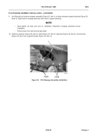
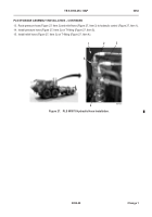
21. Route RH and LH twistlock sensor harnesses (Figure 30, Item 1) from stowage assembly (Figure 30, Item 2),
along interior of left side of frame (Figure 30, Item 4) to rear of vehicle. Route each sensor harness to rear of
vehicle.
22. Install new tiedown straps (Figure 30, Item 3) as required to attach twistlock sensor harnesses (Figure 30,
Item 1) to existing hoses along frame (Figure 30, Item 4).
Figure 30.
Twistlock Sensor Harness Installation.
052
467-117
2
3
4
1
Back to Top

