TB-9-3950-253-13-P
PALLETIZED LOAD SYSTEM TRUCK, M1075 and M1075A1 (PLS) AND HEAVY EXPANDED MOBILITY TACTICAL TRUCK, M1120, M1120A2, AND M1120A4 (HEMTT), ENHANCED CONTAINER HANDLING UNIT (E-CHU)
TECHNICAL BULLETIN; OPERATOR AND FIELD MAINTENANCE, INSTALLATION INSTRUCTIONS, AND REPAIR PARTS AND SPECIAL TOOLS LIST
JULY 2009
TB-9-3950-253-13-P - Page 545 of 704
0052-35
Change 1
TB 9-3950-253-13&P
0052
PLS STOWAGE ASSEMBLY INSTALLATION – CONTINUED
NOTE
Rear edge of stowage assembly must be positioned 3 1/8 in. (80 mm) from front edge of
stowed hook arm. Measure distance on right and left sides of hook arm for accurate
placement of stowage assembly.
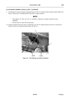
33. Adjust placement of stowage assembly (Figure 33, Item 1) on frame until distance between stowage assembly
and front edge of hook arm (Figure 33, Item 2) measures 3 1/8 in. (80 mm).
Figure 33.
Distance Between Stowage Assembly and Hook Arm.
052
34. Tighten 12 bolts and nuts securing stowage assembly to right and left support brackets.
35. Tighten 14 bolts and nuts securing right and left support brackets to frame.
36. Return hook arm to home position (TM 9-2320-364-14&P).
467-110
2
1
Back to Top


