TB-9-3950-253-13-P
PALLETIZED LOAD SYSTEM TRUCK, M1075 and M1075A1 (PLS) AND HEAVY EXPANDED MOBILITY TACTICAL TRUCK, M1120, M1120A2, AND M1120A4 (HEMTT), ENHANCED CONTAINER HANDLING UNIT (E-CHU)
TECHNICAL BULLETIN; OPERATOR AND FIELD MAINTENANCE, INSTALLATION INSTRUCTIONS, AND REPAIR PARTS AND SPECIAL TOOLS LIST
JULY 2009
TB-9-3950-253-13-P - Page 554 of 704
TB 9-3950-253-13&P
Change 1
0052-44
0052
TWISTLOCK SENSOR INSTALLATION
00052
NOTE
•
Twistlock sensor installation is the same for both HEMTT and PLS.
•
Perform steps 1 through 4 for both right and left sides.
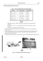
1. Remove locking pin (Figure 42, Item 2) from twistlock housing (Figure 42, Item 1).
2. If required, pull down twistlock locking pin (
Figure 42
, Item 4) and rotate locking pin to allow movement of
twistlock handle (
Figure 42
, Item 5).
3. Loosen twistlock handle (
Figure 42
, Item 5) until anvil (
Figure 42
, Item 6) can be positioned for removal from
twistlock housing (
Figure 42
, Item 1), and allow twistlock assembly to swing out of twistlock housing.
4. Align locking tube (
Figure 42
, Item 3) with hole in twistlock housing (
Figure 42
, Item 1) and insert locking pin
(
Figure 42
, Item 2) through twistlock housing into locking tube.
Figure 42.
Release Twistlock from Housing.
052
Back to Top


