TB-9-3950-253-13-P
PALLETIZED LOAD SYSTEM TRUCK, M1075 and M1075A1 (PLS) AND HEAVY EXPANDED MOBILITY TACTICAL TRUCK, M1120, M1120A2, AND M1120A4 (HEMTT), ENHANCED CONTAINER HANDLING UNIT (E-CHU)
TECHNICAL BULLETIN; OPERATOR AND FIELD MAINTENANCE, INSTALLATION INSTRUCTIONS, AND REPAIR PARTS AND SPECIAL TOOLS LIST
JULY 2009
TB-9-3950-253-13-P - Page 555 of 704
0052-45
Change 1
TB 9-3950-253-13&P
0052
TWISTLOCK SENSOR INSTALLATION – CONTINUED
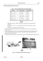
5. Route LH twistlock sensor harness to left-side twistlock assembly (Figure 43, Item 3).
6. Remove two nuts (Figure 43, Item 2) from twistlock sensor (Figure 43, Item 1). Discard nuts.
7. Loosen two bolts (Figure 43, Item 6) in cable clamp (Figure 43, Item 4) and insert twistlock sensor (Figure 43,
Item 1) into clamp.
8.
Adjust twistlock sensor placement until end of sensor is .0625 to .1875 in. (2 to 3 mm) from twistlock plate (Figure
43, Item 5) and tighten two bolts (Figure 43, Item 6) in cable clamp (Figure 43, Item 4).
Figure 43.
Adjust Twistlock Sensor.
052
9. Install new tiedown straps (Figure 44, Item 3) securing twistlock harnesses (Figure 44, Item 2) to slider
assembly (Figure 44, Item 1). Roll any excess harness and secure to frame with tiedown straps.
Figure 44.
Secure Harnesses to Slider Assembly.
052
END OF TASK
1
6 (HIDDEN)
5
4
3
2
1
1
3
3
2
Back to Top


