TB-9-3950-253-13-P
PALLETIZED LOAD SYSTEM TRUCK, M1075 and M1075A1 (PLS) AND HEAVY EXPANDED MOBILITY TACTICAL TRUCK, M1120, M1120A2, AND M1120A4 (HEMTT), ENHANCED CONTAINER HANDLING UNIT (E-CHU)
TECHNICAL BULLETIN; OPERATOR AND FIELD MAINTENANCE, INSTALLATION INSTRUCTIONS, AND REPAIR PARTS AND SPECIAL TOOLS LIST
JULY 2009
TB-9-3950-253-13-P - Page 560 of 704
TB 9-3950-253-13&P
Change 1
0052-50
0052
HOOK ARM SENSOR INSTALLATION – CONTINUED
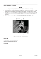
3. Place a straight measurement aid (Figure 49, Item 1) on flat surface of hook arm (Figure 49, Item 2) where it
angles down.
4. Place hook arm switch plate (Figure 49, Item 4) on angled edge of hook arm (Figure 49, Item 2) where distance
between bottom of measurement aid (Figure 49, Item 1) and top angled edge of hook arm switch plate is
1/4 in.
5. Mark edge of hook arm (Figure 49, Item 2) to identify point of placement of switch plate (Figure 49, Item 4) on
hook arm.
WARNING
•
Appropriate safety precautions (including, but not limited to, wearing proper breathing
apparatus, hearing protection, safety goggles, etc.) must be observed when working with
CARC material.
•
Always wear gloves and a face shield or breathing apparatus when drilling painted
surfaces. Airborne particles may cause lung irritation or damage to eyes.
•
Failure to follow these warnings may cause injury or death to personnel.
6. Place switch plate (Figure 49, Item 4) 1 1/4 in. from edge and mark pilot holes. Drill two 1/4 in. holes in hook
arm (Figure 49, Item 2).
7. Install switch plate (Figure 49, Item 4) and two rivets (Figure 49, Item 3) on hook arm (Figure 49, Item 2).
Figure 49.
Hook Arm Sensor Plate Installation.
052
Back to Top


