TB-9-3950-253-13-P
PALLETIZED LOAD SYSTEM TRUCK, M1075 and M1075A1 (PLS) AND HEAVY EXPANDED MOBILITY TACTICAL TRUCK, M1120, M1120A2, AND M1120A4 (HEMTT), ENHANCED CONTAINER HANDLING UNIT (E-CHU)
TECHNICAL BULLETIN; OPERATOR AND FIELD MAINTENANCE, INSTALLATION INSTRUCTIONS, AND REPAIR PARTS AND SPECIAL TOOLS LIST
JULY 2009
TB-9-3950-253-13-P - Page 563 of 704
0052-53
Change 1
TB 9-3950-253-13&P
0052
SENSOR CALIBRATION
00052
WARNING
Do not stand on vehicle while operating LHS. Failure to follow this warning may result in
injury or death to personnel.
1. With MODE switch set to AUTO position, partially extend hook arm (PLS: TM 9-2320-364-14&P, HEMTT:
TM 9-2320-326-14&P) until cylinder arm (Figure 52, Item 1) is extended 28 in. (750 mm) measured from base
of cylinder arm cap (Figure 52, Item 2) to top of cylinder casing (Figure 52, Item 3).
Figure 52.
Hook Arm Cylinder Extension.
052
2. Shut off vehicle and set ignition switch to ON position
(PLS: TM 9-2320-364-14&P, HEMTT:
TM 9-2320-326-14&P).
NOTE
Ensure that stowage control toggle switch is set to OFF position.
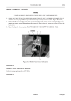
3. Loosen nut (Figure 53, Item 5) on hook arm sensor (Figure 53, Item 2) and adjust nut (Figure 53, Item 4) until
face of sensor is .375 to 0.5 in. (2 to 3 mm) from sensor plate (Figure 53, Item 6).
4. Slide hook arm sensor (Figure 53, Item 2) on bracket (Figure 53, Item 3) toward sensor plate (Figure 53,
Item 6) and identify position where sensor light (Figure 53, Item 1) turns on. Tighten nut (Figure 53, Item 5) at
that position.
467-128
2
1
3
28 IN.
Back to Top


