TB-9-3950-253-13-P
PALLETIZED LOAD SYSTEM TRUCK, M1075 and M1075A1 (PLS) AND HEAVY EXPANDED MOBILITY TACTICAL TRUCK, M1120, M1120A2, AND M1120A4 (HEMTT), ENHANCED CONTAINER HANDLING UNIT (E-CHU)
TECHNICAL BULLETIN; OPERATOR AND FIELD MAINTENANCE, INSTALLATION INSTRUCTIONS, AND REPAIR PARTS AND SPECIAL TOOLS LIST
JULY 2009
TB-9-3950-253-13-P - Page 561 of 704
0052-51
Change 1
TB 9-3950-253-13&P
0052
HOOK ARM SENSOR INSTALLATION – CONTINUED
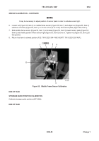
8. Route hook arm wiring harness (Figure 50, Item 3) through opening in hook arm (Figure 50, Item 1) to hook
arm sensor bracket (Figure 50, Item 5).
CAUTION
Install sensor so that face is flush with outer nut. Failure to follow this caution may result in
damage to equipment.
NOTE
Sensor position in bracket will be calibrated later in this work package.
9. Remove nut (Figure 50, Item 6) from hook arm sensor (Figure 50, Item 2) and install hook arm sensor and nut
in hook arm sensor bracket (Figure 50, Item 5), so that face of sensor is flush with nut.
10. Install new tiedown straps (Figure 50, Item 4) as required.
Figure 50.
Hook Arm Sensor Installation.
052
6
3
5
3
1
2
4
Back to Top


