TB-9-3950-253-13-P
PALLETIZED LOAD SYSTEM TRUCK, M1075 and M1075A1 (PLS) AND HEAVY EXPANDED MOBILITY TACTICAL TRUCK, M1120, M1120A2, AND M1120A4 (HEMTT), ENHANCED CONTAINER HANDLING UNIT (E-CHU)
TECHNICAL BULLETIN; OPERATOR AND FIELD MAINTENANCE, INSTALLATION INSTRUCTIONS, AND REPAIR PARTS AND SPECIAL TOOLS LIST
JULY 2009
TB-9-3950-253-13-P - Page 557 of 704
0052-47
Change 1
TB 9-3950-253-13&P
0052
MIDDLE FRAME SENSOR INSTALLATION – CONTINUED
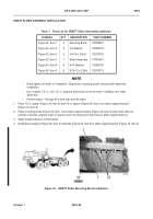
1. Install screw (Figure 45, Item 2) in pivot cylinder (Figure 45, Item 1).
NOTE
Position sensor plate as shown in Figure 45.
2. Install sensor plate (
Figure 45
, Item 3) and locknut (
Figure 45
, Item 4) on screw (
Figure 45
, Item 2).
Figure 45.
Middle Frame Sensor Plate Installation.
052
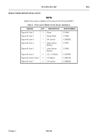
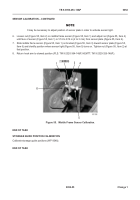
3. Measure and mark 5 1/4 in. from left edge of middle frame (Figure 46, Item 1).
4. Install upper sensor bracket (Figure 46, Item 2), lower sensor bracket (Figure 46, Item 3), three washers
(Figure 46, Item 5), bolts (Figure 46, Item 4), washers (Figure 46, Item 6), and locknuts (Figure 46, Item 7) on
middle frame (Figure 46, Item 1), aligning left edge of sensor bracket with 5 1/4 in. mark.
1
2
3
4
5
Back to Top


