TB-9-3950-253-13-P
PALLETIZED LOAD SYSTEM TRUCK, M1075 and M1075A1 (PLS) AND HEAVY EXPANDED MOBILITY TACTICAL TRUCK, M1120, M1120A2, AND M1120A4 (HEMTT), ENHANCED CONTAINER HANDLING UNIT (E-CHU)
TECHNICAL BULLETIN; OPERATOR AND FIELD MAINTENANCE, INSTALLATION INSTRUCTIONS, AND REPAIR PARTS AND SPECIAL TOOLS LIST
JULY 2009
TB-9-3950-253-13-P - Page 547 of 704
0052-37
Change 1
TB 9-3950-253-13&P
0052
PLS STOWAGE ASSEMBLY INSTALLATION – CONTINUED
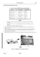
38. Place stowage control bracket (Figure 35, Item 11) on left-side fender (Figure 35, Item 12) aligning bottom left
hole in bracket with hole in fender.
WARNING
•
Appropriate safety precautions (including, but not limited to, wearing proper breathing
apparatus, hearing protection, safety goggles, etc.) must be observed when working with
CARC material.
•
Always wear gloves and a face shield or breathing apparatus when drilling painted
surfaces. Airborne particles may cause lung irritation or damage to eyes.
•
Failure to follow these warnings may cause injury or death to personnel.
39. Mark location of remaining three holes in bracket (Figure 35, Item 11) on fender (Figure 35, Item 12). Drill three
0.5 in. holes at marked locations.
40. Install stowage control panel bracket (Figure 35, Item 11), four bolts (Figure 35, Item 7), washers (Figure 35,
Item 8), washers (Figure 35, Item 9), and locknuts (Figure 35, Item 10) on fender (Figure 35, Item 12).
41. Install stowage control backplate (Figure 35, Item 2) and four bolts (Figure 35, Item 13) on stowage control
panel (Figure 35, Item 1).
42. Install stowage control panel backplate (Figure 35, Item 2), two bolts (Figure 35, Item 3), washers (Figure 35,
Item 4), washers (Figure 35, Item 5), and locknuts (Figure 35, Item 6) on stowage control panel bracket
(Figure 35, Item 11).
Figure 35.
Stowage Control Panel and Bracket.
052
END OF TASK
Back to Top

