TM-5-2350-377-14-P - Page 162 of 335
TM 5-2350-377-14&P
DISASSEMBLY
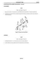
1. Remove two straight adapters (item 4) on ports 1A on top and bottom valve bodies (item 3).
Figure 52.
Flow Valves.
2. Remove eight straight adapters (item 1) on remaining valve ports on valve bodies (item 2 and 3).
ASSEMBLY
1. Install two straight adapters (item 4) on ports 1A on top and bottom valve bodies (item 3).
2. Install eight straight adapters (item 1) on remaining valve body ports on valve bodies (item 2 and 3).
END OF WORK PACKAGE
HYDRAULIC FITTINGS REPLACEMENT
0025 00
0025 00-1/2 blank
INITIAL SETUP
Tools/Test Equipment
Tool kit, general mechanic's
(Item 6, WP 0056 00)
Shop equipment, common no. 1
(Item 2, WP 0056 00)
Wrench set, open end
(Item 8, WP 0056 00)
Wrench set, crowfoot
(Item 7, WP 0056 00)
Equipment Conditions
Hydraulic pressure relieved
(TM 5-2350-262-20-1)
Hydraulic hoses removed
(WP 0027 00, Disassembly)
Right, center, and left rear floor plates removed
(TM 5-2350-262-10)
1
1
1
1
1
1
2
1
1
1
1
1
3
1
2
3
4
4
Back to Top


