TM-9-2320-283-13-P - Page 106 of 400
0018-4
TM 9-2320-283-13&P
0018
1
2
3
4
1
5
6
2
3
4
Figure 6. Removing Wheels from Front Axle Hubs.
END OF TASK
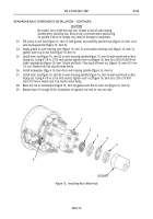
Figure 7. Removing Rear Brake Drums.
REMOVING WHEELS – CONTINUED
10.
Using suitable impact wrench and socket, remove 10 lug nuts (figure 6, item 1) and wheel and tire
assembly (figure 6, item 3) from wheel studs (figure 6, item 2) and front axle hub (figure 6, item 4).
11.
Repeat step 10 to remove opposite wheel and tire assembly from front axle hub (figure 6, item 4).
REAR-REAR AXLE COMPONENTS INSTALLATION
1.
Depress and rotate screw (figure 7, item 5) on slack adjuster (figure 7, item 6) until brake drum
(figure 7, item 2) can be rotated freely at both ends of rear-rear axle (figure 7, item 1).
WARNING
Two personnel are required to remove brake drum from hub. Brake
drum weighs 85 lbs (39 kg). Failure to comply may result in injury to
personnel. Seek medical attention in the event of an injury.
NOTE
In order to remove brake drum, it may be necessary to strike the
drum with a hammer to free it from hub flange.
2.
Carefully slide brake drum (figure 7, item 2) off wheel studs (figure 7, item 3) and remove from hub
(figure 7, item 4) at both ends of rear-rear axle (figure 7, item 1).
Back to Top


