TM-9-2320-283-13-P - Page 108 of 400
0018-6
TM 9-2320-283-13&P
0018
1 (BW801543)
2 (801543)
3 (CM103620H)
1
2
3
4
5
REAR-REAR AXLE COMPONENTS INSTALLATION – CONTINUED
9.
Remove two locknuts, (figure 10, item 4), washers (figure 10, item 3), and screws (figure 10, item 5)
from top two holes in axle housing and brake spider (figure 10, item 1). Retain washers
(figure 10, item 3) and discard locknuts (figure 10, item 4) and screws (figure 10, item 5).
WARNING
Metal shavings are sharp and may fly out during reaming operations.
Wear eye protection when enlarging hole with reamer. Failure to
comply may result in injury to personnel. Seek medical attention in
the event of an injury.
CAUTION
Protect spindle shaft when enlarging hole in brake spider and axle
housing. Ensure all metal shavings are cleaned from spindle and
brake spider. Failure to comply may result in damage to equipment.
10.
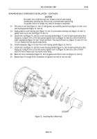
Using 11/16 in. (17.5 mm) reamer, enlarge existing hole (figure 10, item 2) between top two holes in
axle housing and brake spider (figure 10, item 1).
Figure 10. Enlarging Hole in Brake Spider.
11.
Install new clamp sleeve (figure 11, item 2) and new sensor (figure 11, item 1) on new sensor mounting
bracket (figure 11, item 3). Slide sensor (figure 11, item 1) approximately half way in clamp sleeve
(figure 11, item 2).
Figure 11. Installing Wheel Sensor on Sensor Bracket.
Back to Top


