TM-9-2320-283-13-P - Page 107 of 400
0018-5
TM 9-2320-283-13&P
0018
1
2
3
4
1
2
3
4
5
SOCKET
6
7
8
REAR-REAR AXLE COMPONENTS INSTALLATION – CONTINUED
WARNING
Leaking or spilled oil may cause a slip and fall hazard. Clean any
leaking or spilled oil immediately, using suitable fluid absorbent
materials. Dispose of contaminated cloths, rags, or cleaning materials
in accordance with local procedures and plans. Failure to comply
may result in injury to personnel. Seek medical attention in the event
of an injury.
NOTE
In order to remove the axle shaft, it may be necessary to strike the
axle shaft flange with a hammer to free it from the hub.
3.
Position clean, dry drain pan under rear-rear axle hub (figure 8, item 1), and remove eight locknuts
(figure 8, item 4), washers (figure 8, item 3), and axle shaft (figure 8, item 2) from hub
(figure 8, item 1). Discard locknuts (figure 8, item 4).
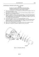
Figure 8. Removing Axle Shaft.
5.
Bend tabs on lockwasher (figure 9, item 4) away from outer nut (figure 9, item 5). Using 4-1/8 in.
(105 mm) socket, remove outer nut (figure 9, item 5), lockwasher (figure 9, item 4), and inner nut
(figure 9, item 6) from axle housing spindle (figure 9, item 8). If tabs are broken, replace lockwasher
(figure 9, item 4).
6.
Remove outer bearing cone (figure 9, item 7) and rear wheel hub (figure 9, item 3) from axle housing
spindle (figure 9, item 8).
NOTE
Bearing cups will not be removed from rear wheel hub and are
discarded with hub.
7.
Using suitable drift and hammer, remove seal (figure 9, item 1) and inner bearing cone (figure 9, item 2)
from rear wheel hub (figure 9, item 3). Discard seal (figure 9, item 1) and rear wheel hub
(figure 9, item 3).
8.
Repeat steps 3 through 7 to remove opposite axle shaft and hub assembly from rear-rear axle.
Figure 9. Removing Hub and Wheel Bearings.
Back to Top


