TM-9-2320-283-13-P - Page 115 of 400
0018-13
TM 9-2320-283-13&P
0018
1
2
3
4
5
6
7
1
8
7
3
1
2
3
4
5
6
7
8
9
10
FRONT AXLE COMPONENTS INSTALLATION – CONTINUED
WARNING
Retaining springs may fly out with extreme force during removal of
brake shoes. Wear eye protection when removing brake shoes.
Failure to comply may result in injury to personnel. Seek medical
attention in the event of an injury.
3.
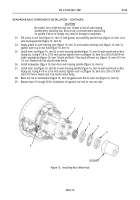
Using suitable pry bar, lift upper and lower brake shoes (figure 21, items 1 and 7) at camshaft
(figure 21, item 2) one at a time, and remove two shoulder pins (figure 21, item 5) and rollers
(figure 21, item 4) from between camshaft (figure 21, item 2) and brake shoes (figure 21, items 1 and 7).
4.
Disconnect shoe release spring (figure 21, item 3) from pin (figure 21, item 6) on lower brake shoe
(figure 21, item 7), and remove upper and lower brake shoes (figure 21, items 1 and 7) and two shoe
retaining springs (figure 21, item 8) together as an assembly, as shown in figure 21.
5.
Repeat steps 3 and 4 for removal of opposite front brake shoes (figure 21, items 1 and 7).
Figure 21. Removing Front Brake Shoes.
6.
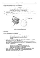
Position clean, dry drain pan under front hub (figure 22, item 2), and remove six bolts (figure 22, item 10),
lockwashers (figure 22, item 9), cap (figure 22, item 8), and gasket (figure 22, item 7) from front hub (figure
22, item 2). Discard gasket (figure 22, item 7), lockwashers (figure 22, item 9), bolts
(figure 22, item 10), and cap (figure 22, item 8).
7.
Remove cotter pin (figure 22, item 6), slotted nut (figure 22, item 5), and key washer (figure 22, item 4)
from spindle (figure 22, item 1). Discard cotter pin (figure 22, item 6).
8.
Remove outer bearing cone (figure 22, item 3), and front hub (figure 22, item 2) from spindle
(figure 22, item 1).
Figure 22. Removing Front Hub.
Back to Top


