TM-9-2320-283-13-P - Page 109 of 400
0018-7
TM 9-2320-283-13&P
0018
1 (W344910)
2
3
4 (CM103620H)
5 (W391024)
6
7
1 (W26681)
(W26764)
2 (PHM5023)
3
4
5
6
REAR-REAR AXLE COMPONENTS INSTALLATION – CONTINUED
12.
Route wheel sensor power cable (figure 12, item 7) through enlarged hole (figure 12, item 3), and install
sensor mounting bracket (figure 12, item 4) on axle housing and brake spider (figure 12, item 6) with
two new bolts (figure 12, item 5), washers (figure 12, item 2) retained in step 9, and new locknuts
(figure 12, item 1).
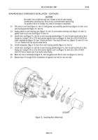
Figure 12. Installing Wheel Sensor on Brake Spider.
13.
Measure and cut new bulk split loom (figure 13, item 2) to length of wheel sensor power cable
(figure 13, item 3), and install split loom (figure 13, item 2) on power cable (figure 3, item 3).
CAUTION
To protect wheel sensor power cable, ensure split loom is positioned
through enlarged hole in brake spider during installation. Failure to
comply may result in damage to equipment.
14.
Slide end of split loom (figure 13, item 2) into enlarged hole (figure 13, item 5), and secure split loom
(figure 13, item 2) to camshaft bracket (figure 13, item 6) with two new tie straps (figure 13, item 1).
15.
Repeat steps 9 through 14 to install new wheel sensor assembly (figure 13, item 4) at opposite end of
rear-rear axle.
Figure 13. Installing Split Loom on Wheel Sensor Power Cable.
Back to Top


