TM-9-2320-283-13-P - Page 110 of 400
0018-8
TM 9-2320-283-13&P
0018
1 (GUNW1322R)
(GUNW1322L)
2 (GUNW1438)
3 (GUNHR936K)
4
WOOD BLOCK
HAMMER
REAR-REAR AXLE COMPONENTS INSTALLATION – CONTINUED
NOTE
Ensure new inner and outer bearing cups are installed on new rear
wheel hub.
Ensure the same right-hand or left-hand threaded wheel studs are
installed on the same hub. Ensure each wheel stud is driven in until
shoulder is fully seated against hub flange.
16.
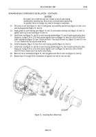
Position new rear hub (figure 14, item 3) facing down on rear brake drum (figure 14, item 4) with wheel
stud holes aligned.
17.
Install 10 new right-hand threaded studs (figure 14, item 1) on rear hub (figure 14, item 3).
18.
Repeat steps 16 and 17 to install new left-hand threaded studs on opposite new rear hub.
CAUTION
Use caution not to bend or distort tone ring during installation. Tone
ring must turn true with hub after installation. Ensure tone ring is
fully seated on hub. Failure to comply may result in damage to
equipment.
19.
Using block of wood and hammer, drive rear tone ring (figure 14, item 2) on rear hub (figure 14, item 3)
until seated.
Figure 14. Installing Wheel Studs and Rear Tone Ring.
Back to Top


