TM-9-2320-283-13-P - Page 113 of 400
0018-11
TM 9-2320-283-13&P
0018
1
5
2
3 (274639)
4
1
2
REAR-REAR AXLE COMPONENTS INSTALLATION – CONTINUED
30.
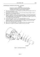
Remove old adhesive from axle shaft flange (figure 17, item 1), clean surface, and apply new adhesive
to axle shaft flange (figure 17, item 1).
31.
Install axle shaft (figure 17, item 4) on rear hub (figure 17, item 5) with eight washers (figure 17, item 2),
and new locknuts (figure 17, item 3).
32.
Position suitable tanker bar to prevent rear hub (figure 17, item 5) from turning clockwise, and tighten
eight locknuts (figure 17, item 3) to 90–120 lb-ft (122–163 N•m).
Figure 17. Installing Axle Shaft.
CAUTION
To protect wheel sensor power cable, ensure split loom is positioned
through enlarged hole in brake spider after positioning wheel sensor.
Failure to comply may result in damage to equipment.
33.
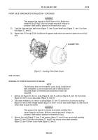
Push wheel sensor (figure 18, item 1) in until it contacts tone ring (figure 18, item 2).
Figure 18. Positioning Wheel Sensor.
Back to Top


