TM-9-2320-283-13-P - Page 112 of 400
0018-10
TM 9-2320-283-13&P
0018
1
2
3
4
5
SOCKET
6
REAR-REAR AXLE COMPONENTS INSTALLATION – CONTINUED
CAUTION
Be careful not to slide hub seal over threads at end of axle housing
spindle when installing hub. Ensure hub is centered when positioning
on spindle. Failure to comply may result in damage to equipment.
23.
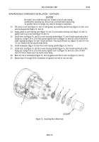
Fill cavity in rear hub (figure 16, item 1) with grease, and carefully position hub (figure 16, item 1) on
axle housing spindle (figure 16, item 6).
24.
Apply grease to outer bearing cone (figure 16, item 2), and position bearing cone (figure 16, item 2)
against outer cup in rear hub (figure 16, item 1).
25.
Install inner nut (figure 16, item 3) on axle housing spindle (figure 16, item 6) with machined surface
facing out. Using 4-1/8 in. (105 mm) socket, tighten inner nut (figure 16, item 3) to 50 lb-ft (68 N•m)
while rotating hub (figure 16, item 1) back and forth. Then back off inner nut (figure 16, item 2) 1/4 to
1/3 turn. Rotate hub; hub should rotate freely.
26.
Install lockwasher (figure 16, item 4) on axle housing spindle (figure 16, item 6).
27.
Install outer nut (figure 16, item 5) on axle housing spindle (figure 16, item 6) with machined surface
facing out. Using 4-1/8 in. (105 mm) socket, tighten outer nut (figure 16, item 5) to 250–275 lb-ft
(339–373 N•m). Rotate hub; hub should rotate freely.
28.
Bend one tab on lockwasher (figure 16, item 4) against each flat on outer nut (figure 16, item 5).
29.
Repeat steps 19 through 28 for installation of opposite rear hub on rear-rear axle.
Figure 16. Installing Rear Wheel Hub.
Back to Top


