TM-9-2320-440-13-P - Page 1103 of 1616
TM 9-2320-440-13&P
0155-3
0155
2.
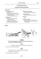
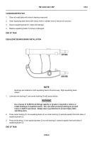
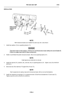
Lubricate threads of two screws (2) with lubricating oil and install longitudinal torque rod (4) on axle mount (5)
with four washers (3), two screws (2), and locknuts (1). Tighten locknuts (1) to 170 lb-ft (231 N•m).
END OF TASK
LATERAL TORQUE ROD REMOVAL
-
-
-
-
-
-
-
-
-
-
-
-
-
-
-
-
-
-
-
-
-
-
-
-
-
-
-
-
-
-
-
-
-
-
-
-
-
NOTE
•
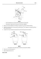
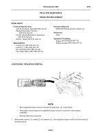
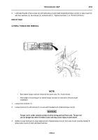
Both lateral torque rods are removed the same way.
No. 4 axle shown.
•
Note angle of mounting pin on lateral torque rod prior to removal to ensure proper
installation.
1.
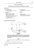
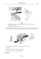
Loosen two locknuts (1).
2.
Loosen locknut (2) until locknut (2) is even with threaded end of lateral torque rod (3).
WARNING
Torque rod is under extreme pressure when being pressed from axle. Torque rod
can be dangerous when it breaks loose and may cause injury to personnel.
3.
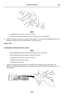
Soldier A uses hand jack to press tapered end of lateral torque rod (3) from axle mount (4) while Soldier B
strikes axle mount (4) with soft-faced hammer.
THAAD0388
Back to Top

