TM-9-2330-227-14-P - Page 136 of 576
TM 9-2330-227-14&P
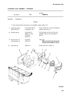
CLEARANCE LIGHT ASSEMBLY
This task covers:
a. Removal (page 4-58)
b. Installation (page 4-60)
INITIAL SETUP
Tools
Materials/Parts
Knife, putty
Cloth, crocus (item 5, appendix E)
Ladder, extension
Screwdriver, cross-tip, number two
Personnel Required
Screwdriver, flat-tip, 3/16-inch
One
ACTION
LOCATION
ITEM
REMARKS
NOT E
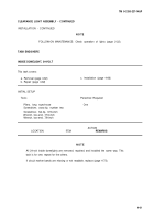
All clearance and blackout lights are removed and installed the same way. This task is
for one; repeat for the others.
If wire connectors are to be replaced or repaired, go to wire connector procedure
(page 4-71).
REMOVAL
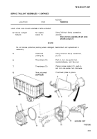
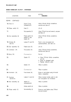
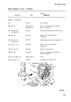
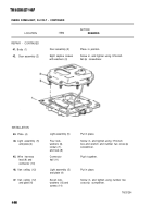
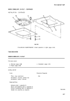
1.
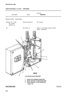
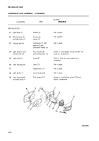
Lens housing (1)
Two screws (3)
Using 3/16-inch flat-tip screwdriver,
and light body (2)
unscrew and take out.
2.
Light body (2)
Lens housing (1)
Take off.
3.
Lens housing (1)
Speed nut (4)
Using 3/16-inch flat-tip screwdriver,
pry off.
4.
Lens (5)
Pull out.
5.
Light body (2)
Lamp (6)
a. Push in, turn one-quarter turn
counterclockwise, and take out.
b. Inspect for broken filament and
corrosion.
If corroded, clean with crocus cloth.
6.
Socket (7)
Check for corrosion.
If corroded, clean with crocus cloth.
4-58
Back to Top

