TM-9-2330-342-23-P - Page 969 of 1348
INSTALLATION - Continued
1
2
3
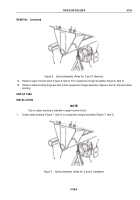
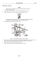
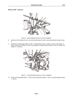
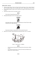
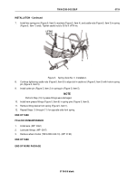
Figure 9.
Spring Assembly (Axles No. 2 and 3) Installation.
8.
Install two U-bolts (Figure 9, Item 1) around top plate (Figure 9, Item 2) and spring assembly (Figure 9, Item
3).
9.
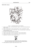
Install lower trunnion block (Figure 10, Item 1), eight washers (Figure 10, Item 3), and four nuts (Figure 10,
Item 2) on two U-bolts (Figure 10, Item 4) and suspension hanger assembly (Figure 10, Item 5). Tighten nuts
to 880 lb-ft (1193 N·m).
1
2
3
4
5
Figure 10.
Spring Assembly (Axles No. 2 and 3) Installation.
10.
Position two rubber pads (Figure 11, Item 5) and cap spring seat (Figure 11, Item 3) on spring assembly (Figure
11, Item 6).
TM 9-2330-342-23&P
0118
0118-7
Back to Top

