TM-9-2330-342-23-P - Page 970 of 1348
INSTALLATION - Continued
1
2
3
4
5
6
7
8
9
10
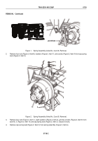
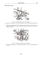
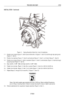
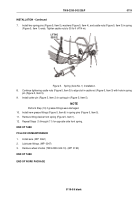
Figure 11.
Spring Assembly (Axles No. 2 and 3) Installation.
11.
Position two U-bolts (Figure 11, Item 9) around Axle No. 2 (Figure 11, Item 10) and through cap spring seat
(Figure 11, Item 3).
12.
Position four washers (Figure 11, Item 2) and locknuts (Figure 11, Item 1) on U-bolts (Figure 11, Item 9).
13.
Position four screws (Figure 11, Item 4), washers (Figure 11, Item 7), and locknuts (Figure 11, Item 8) through
cap spring seat (Figure 11, Item 3).
14.
Align axle No. 2 (WP
0062) and align axle No. 3 (WP
0063).
15.
Tighten four locknuts (Figure 11, Item 8) on screws (Figure 11, Item 4) to 180 lb-ft (244 N·m).
16.
Tighten four locknuts (Figure 11, Item 1) on U-bolts (Figure 11, Item 9) to 300 lb-ft (407 N·m).
17.
Repeat Steps (1) through (16) for axle No. 3 (Figure 11, Item 10).
WARNING
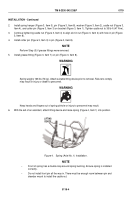
Rear of the trailer weighs approximately 8,000 lbs (3,632 kg). Attach suitable lifting device
prior to lifting or lowering frame. Failure to comply may result in injury or death to personnel.
18.
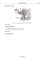
Remove jackstands from suspension hanger assembly (Figure 12, Item 1).
TM 9-2330-342-23&P
0118
0118-8
Back to Top


