TM-9-2330-356-14
SEMITRAILER, TANK: 5000 GALLON, BULK HAUL, SELF LOAD/UNLOAD M967 AND M967A1; SEMITRAILER, TANK: 5000 GALLON, FUEL DISPENSING, AUTOMOTIVE M969 AND M969A1; SEMITRAILER, TANK: 5000 GALLON, FUEL DISPENSING, UNDER/OVERWING AIRCRAFT M970 AND M970A1
TECHNICAL MANUAL; OPERATOR’S, UNIT, DIRECT SUPPORT, AND GENERAL SUPPORT MAINTENANCE MANUAL
OCTOBER 1990
TM-9-2330-356-14 - Page 225 of 528
TM 9-2330-356-14
(2) Check for leakage indicated by bubbles. No
leakage is permissible.
CAUTION
DO NOT ovetighten clamp on air chamber.
Maximum torque should be 20-25 lb.-ft. Ov-
er-tightening will distort the flange and cause
more leakage.
(3) If leakage is found at flange, tighten the
clamp. If leakage is found at connections, tighten fittings.
(4) After initial brake application forces out a
small amount of air, no air should be expelled from the air
chamber. If air continues to exhaust, repair or
replacement of the air chamber is necessary.
b.
Removal.
(1) Disconnect brake hoses from brake chambers
or relay valve.
(2) Remove U-bolt and two nuts securing
chamber to bracket.
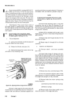
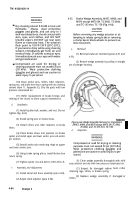
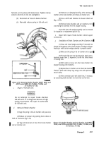
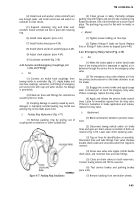
(3) Use adrift (fig. 4-70), or other blunt tool, and
hammer to loosen the collet nut.
NOTE
It may be necessary to remove the whole
brake assembly from the axle before un-
screwing the brake chamber, due to possible
bracket interference.
(4) Remove brake chamber by unscrewing it from
plunger housing.
(5) At this time the wedge assembly can be
removed for inspection or replacement (para 4-35).
c.
Repair.
Refer repair of brake chamber to direct
support maintenance.
d.
Installation.
(1) Check position of the wedge in plunger
housing to make certain wedge assembly is properly
seated (para 4-35).
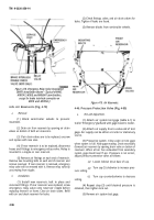
(2) Thread collet nut (fig. 4-70) onto housing
tube. Apply a non-hardening sealer (item 25, Appendix E)
to the first three threads of the housing tube.
(3) With collet nut loose, turn the brake chamber
into the plunger housing until it bottoms.
(4) Aline connection ports with brake lines, if
necessary, by unscrewing brake chamber not more than
one full turn.
(5) Install U-bolt and two nuts to secure brake
chamber to bracket.
(6) Connect brake line.
(7) Make and hold a full pressure brake
application. Hand tighten the collet nut. With a drift and
hammer tighten collet nut 1½-teeth or additional 3/18 of a
turn. Release brake pressure.
(8) Check for leaks at flange and connections
(step
a).
4-38.
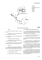
Brake Air Chamber Test and Replacement,
M967A1, M969A1, and M970A1 including
M970 SN TC-0843, TC-0844, and TC-103 thru
TC-178 (Fig. 4-71).
a.
Test.
(1) With towing vehicle connected and vehicle
brakes applied, coat the flanges and connections on the air
chamber with soapy water.
Figure 4-70. Removing Brake Chamber (M967, M969, and
(2)
Check for leakage indicated by bubbles. No
M970 except M970 SN TC-0843, TC-0844, and TC-103 thru
leakage is permissible.
TC-178).
Change 3
4-89
Back to Top

